Shandong Xincheng Pipe Co., Ltd. is one of the most reliable manufacturers and suppliers of black dredging flanged hdpe pipe in China, also supports customized service. Welcome to buy premium black dredging flanged hdpe pipe for sale here from our factory. If you have any enquiry about free sample, please feel free to email us.
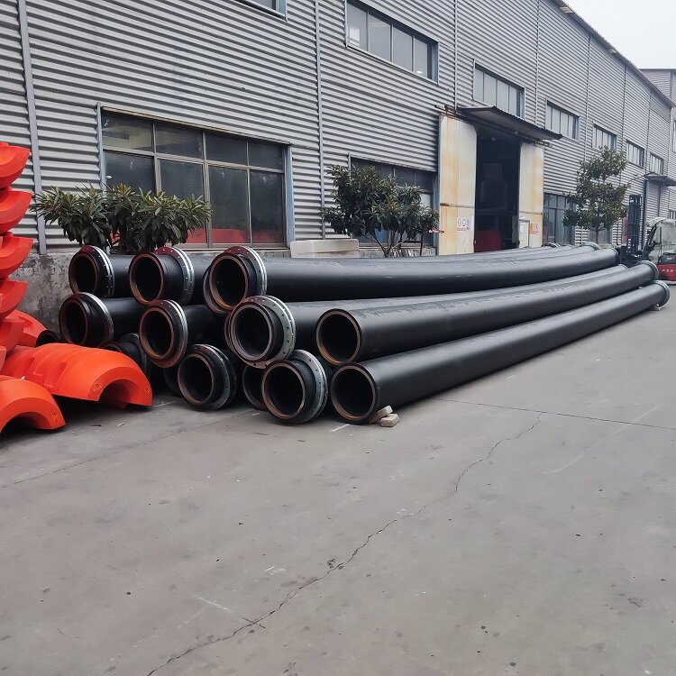
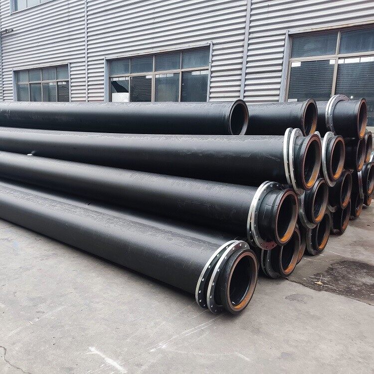
Structure and Connection of Dredging HDPE Pipes
1. Enlarged end, or flare end some people call, No welding required.
2. Nodular cast Iron inserts at end to protect it from deformation,breaking and leakage
3. Loose flang rings (carbon steel, galvanized) at both ends
4. Rubber gasket in between when two pipes are connected by bolts and nuts.

Advantages of Black Dredging Flanged HDPE Pipe
1. Lightweight and flexible: Dredging flanged HDPE pipes weigh only one eighth of steel pipes, making them easy to install, disassemble, and transport, significantly reducing construction time, and improving work efficiency.
2. Strong corrosion resistance: Flanged HDPE pipes have excellent corrosion resistance and can resist the erosion of various chemicals, including acidic and alkaline solutions and saltwater, making them suitable for a variety of complex environments.
3. High strength: Flanged HDPE pipes have high strength and pressure resistance, can withstand large water and soil pressures, and maintain stable pipeline system operation.
4. Smooth inner and outer walls: The inner wall of the pipeline is smooth, with low frictional resistance, which can improve fluid transport efficiency, reduce energy consumption and operating costs.
5. Extremely strong UV resistance: HDPE pipes have extremely strong UV resistance and aging resistance, and their service life is far longer than that of iron pipes, PVC pipes, nylon pipes and ordinary plastic pipes.
6. Long service life: Under appropriate conditions, HDPE pipes have a very long service life and can adapt to various harsh environments, reducing the frequency of replacement and maintenance.
7. Wide temperature range for use: HDPE pipes have a temperature range of -40 ℃ to 60 ℃ and can adapt to various climatic conditions. Whether used in water or on land for a long time, they can maintain efficient operation
Xincheng manufactures dredging HDPE pipe from OD110mm to 1000mm, the sizes are as following:
|
Outer/mm |
Standard |
||||
|
SDR26 |
SDR21 |
SDR17 |
SDR13.7 |
SDR11 |
|
|
WORKING PRESSURE/MPA |
|||||
|
0.6 |
0.8 |
1.0 |
1.25 |
1.6 |
|
|
WALL THICKNESS/MM |
|||||
|
110 |
4.2 |
5.3 |
6.6 |
8.1 |
10.0 |
|
125 |
4.8 |
6.0 |
7.4 |
9.2 |
11.4 |
|
140 |
5.4 |
6.7 |
8.3 |
10.3 |
12.7 |
|
160 |
6.2 |
7.7 |
9.5 |
11.8 |
14.6 |
|
180 |
6.9 |
8.6 |
10.7 |
13.3 |
16.4 |
|
200 |
7.7 |
9.6 |
11.9 |
14.7 |
18.2 |
|
225 |
8.6 |
10.8 |
13.4 |
16.6 |
20.5 |
|
250 |
9.6 |
11.9 |
14.8 |
18.4 |
22.7 |
|
280 |
10.7 |
13.4 |
16.6 |
20.6 |
25.4 |
|
315 |
12.8 |
15.6 |
19.8 |
24.5 |
30.1 |
|
355 |
13.6 |
16.9 |
21.1 |
26.1 |
32.2 |
|
400 |
15.3 |
19.1 |
23.7 |
29.4 |
36.3 |
|
450 |
17.2 |
21.5 |
26.7 |
33.1 |
40.9 |
|
500 |
19.1 |
23.9 |
29.7 |
36.8 |
45.4 |
|
560 |
21.4 |
26.7 |
33.2 |
41.2 |
50.8 |
|
630 |
24.1 |
30.0 |
37.4 |
46.3 |
57.2 |
|
710 |
27.2 |
33.9 |
42.1 |
52.2 |
|
|
800 |
36 |
38.1 |
47.4 |
58.8 |
|
|
900 |
34.4 |
42.8 |
53.3 |
||
|
1000 |
38.2 |
47.7 |
59.3 |
||


